DesignBuilder Team wins the "Best innovative workflow" award ...here's how we did it!
View a recording of our Webinar to learn more about the 3 step process used in the DesignBuilder Team competition entry.
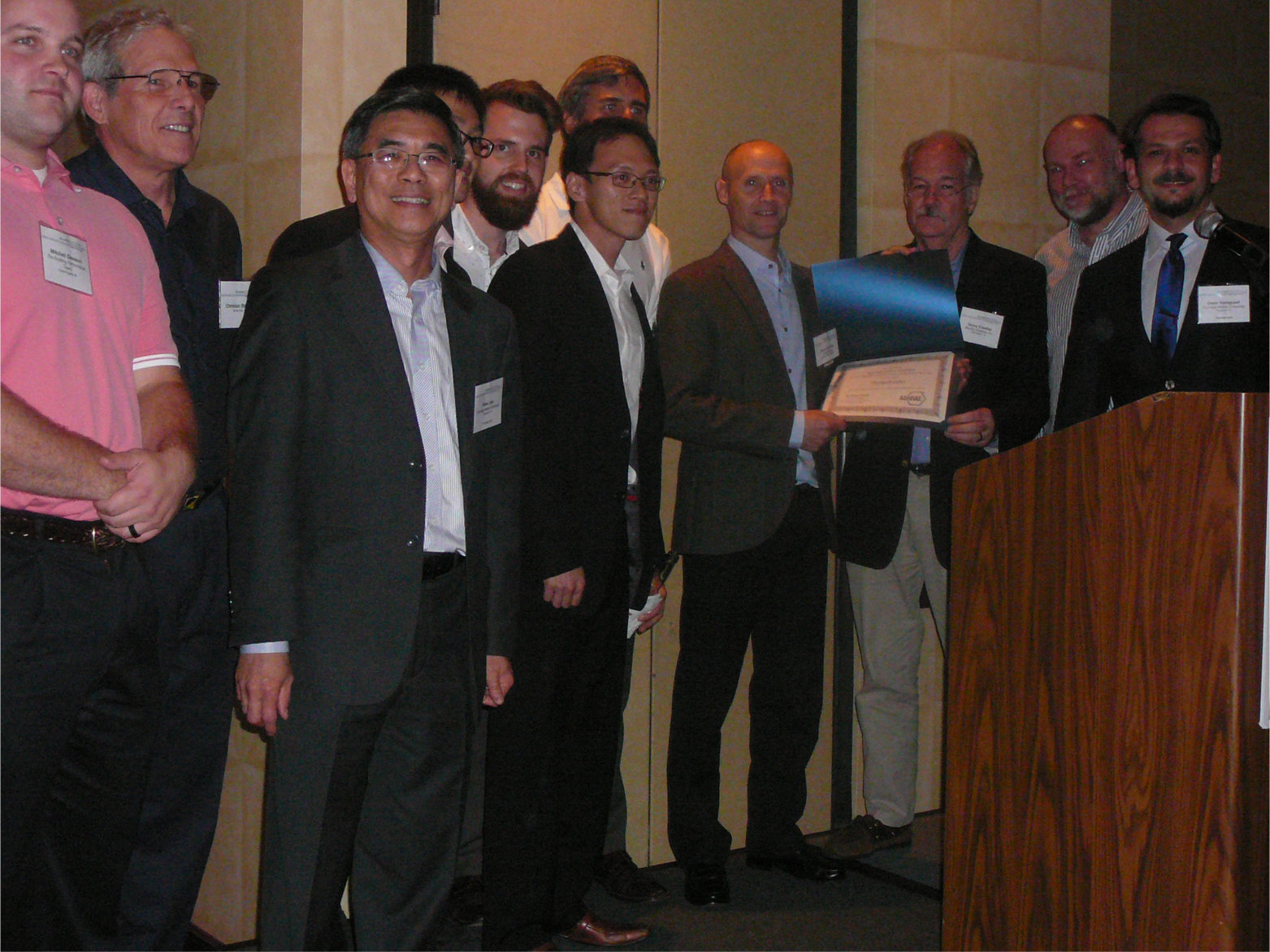
ASHRAE's energy modelling competition
New to the ASHRAE Energy Modeling Conference in 2015 was the LowDown Showdown modelling challenge sponsored by the US Department of Energy and the National Renewable Energy Laboratory. The competition showcased the work of eight mainstream modelling software packages competing to design and model a net-zero or below building.
The challenge set by ASHRAE was for a 53,600 sq ft 3-storey office building with specified requirements such as occupancy density, internal gains and set points. Criteria such as the building location, orientation, form, fabric, glazing, HVAC and lighting systems were left open to competitors.
DesignBuilder team and approach
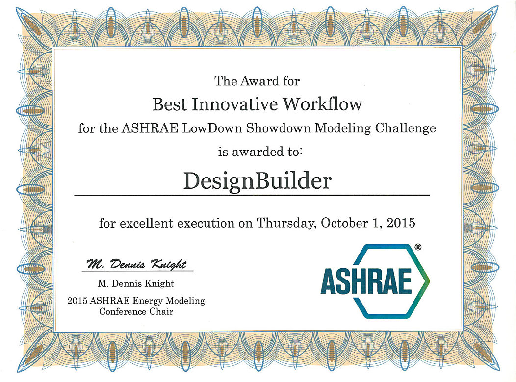
The team was coached by Dave Cocking and Andy Tindale from DesignBuilder and comprised of participants from Arup, Carnegie Mellon University, Atelier Ten, Building Performance Team, Revitaliza Consultores and Sumac:
- David Polson, Holly Stevenson, Arup
- Michael Tillou, Atelier Ten
- Khee Poh Lam, Omer Tugrul Karaguzel, Weili Xu, Adrian Chong, Carnegie Mellon University
- Ignacio Furnies, Revitaliza Consultores
- Gonzalo Lema, Dante Garcia, Billy Condor, Sumac
- Mitchell Gleason, Building Performance Team
- Christian Stalberg, DesignBuilder USA
The first team meeting focused on the general approach and we agreed that we wanted to work on the kind of problem routinely faced by design teams. The location was selected as Pittsburgh (ASHRAE climate zone 5A) which meant that mechanical heating and cooling would be required during the year and that the building could not rely on passive design techniques alone.
We were fortunate that some team members already had detailed data for a development area in Pittsburgh so we were able to site design work in a "real" location. The selected location presented realistic challenges such as a relatively restricted site footprint (meaning we weren't able to simply select any ideal building form for net-zero) and tall surrounding buildings resulting in shading of both glazing and photovoltaic (PV) devices.
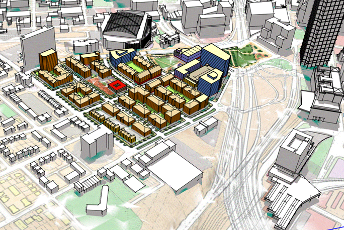
The "real" development site in Pittsburgh.
The project architect also introduced the requirement for mixed-mode (hybrid) conditioning reflecting a typical brief from a client with high sustainability aspirations in Pittsburgh.
The final element of the approach agreed at the outset was that the team would use DesignBuilder's optimisation tools enabling us to ensure that the design would be good value for money through an advanced approach to cost-benefit analysis. Although costed solutions were not required as part of the competition they are required for real projects so we felt that it was important to be able to illustrate cost-optimal solutions in addition to those which would easily achieve net-zero and beyond. Costs were included for all materials and systems used at each stage of the design.
Early-stage design - load reduction optimisation
The preliminary design stage focused on optimising the building form, orientation and fabric to minimise heating and cooling loads. A base model was constructed with all model data, from which a further 6 geometric models were constructed giving a total of 7 building forms to be optimised and compared at the first stage. Six of the forms were constructed to comply with normal design guidelines for mixed-mode buildings using natural ventilation with limits on zone height to depth ratios. For completeness, we also included a traditional "deep plan" [fully conditioned] option with optimal surface area to internal volume ratio for a 3-storey building. The 7 building forms are shown below:
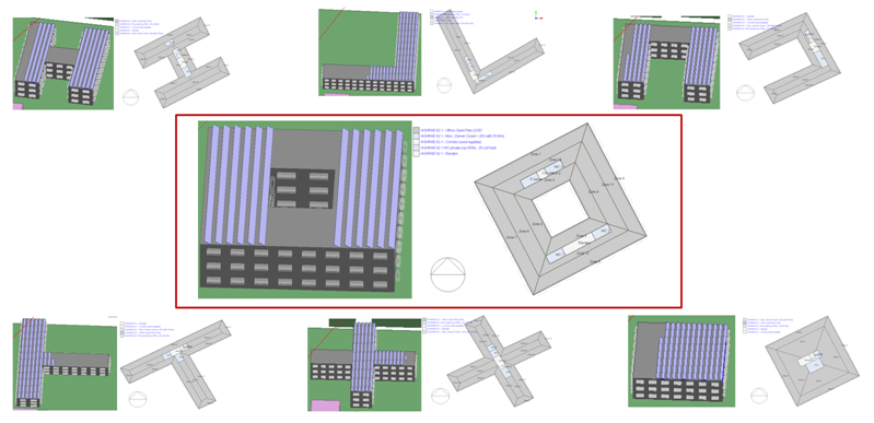
The 7 different building forms optimised to identify minimum loads.
Much of the early work involved setting up the model with the correct ASHRAE 90.1 data including schedules. The competition set challenging requirements for some of the internal gains and we were able to draw on the experience of the Carnegie Mellon University group to produce schedules for gains like elevators and plug loads based on calibrated data from their recent award-winning net-zero project. The basic model data used in each building form was identical.
Before running an optimisation study it is vital to check that your model is working correctly during winter, summer and inter-seasonal conditions. All our models were tested and "sanity-checked" prior to running the optimisations.
Various permutations of model data such as orientation, insulation type and thickness, glazing type and size, external shading and thermal mass were included as design variables. The optimisation objectives were to minimise net site energy and capital expenditure (Capex) and we added a maximum 50 hours discomfort constraint using the ASHRAE 55 80% adaptive comfort metric.
DesignBuilder's optimisation tools use a genetic algorithm to search for the best combination of design variables efficiently, enabling it to find the optimum solutions much more quickly than traditional parametric or systematic approaches. EnergyPlus simulations are run in batches by the optimiser so as to ensure that the best solutions are carried forward to future iterations...the process mimics natural evolution using the principle of "survival of the fittest". Optimisation using a genetic algorithm makes it possible to search the whole solution space quickly and effectively, providing the design team and client with an added level of confidence that all viable solutions have been identified.
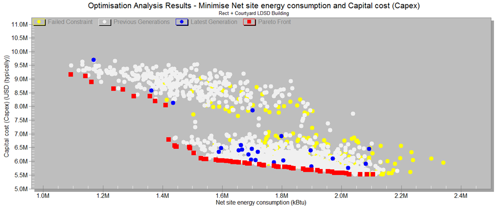
The first optimisations were run using fast simulation servers in the DesignBuilder and Arup offices. The outcome of the first optimisation run was a set of results for each building form similar to that shown below. This shows a range of viable solutions from high-cost low-energy at the top left to low-cost high energy at the bottom right. The red Pareto-optimal points at the leading edge show those designs which pass the comfort constraint and cannot be beaten in terms of the design objectives set. The two main clusters relate to those solutions with Building integrated PV (higher-cost lower net site energy consumption) and those without. All building form options tested included a consistent number of roof PV panels.
The results for each building form were then analysed and overlaid on one plot to identify which yielded the best overall solution.
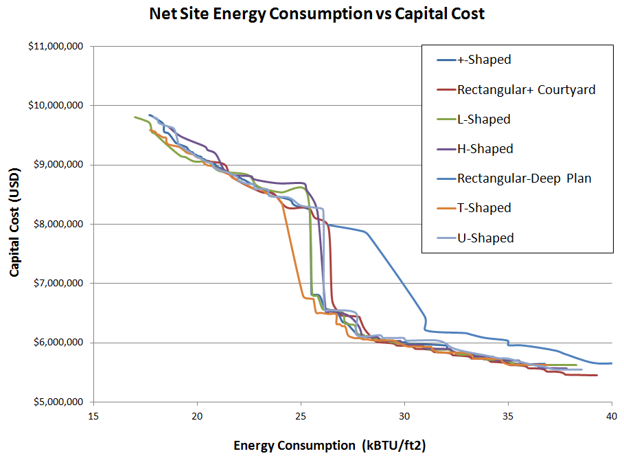
This approach gave the team confidence that we were comparing the optimal solutions for each building form rather than a single set of configurations that would be seen with a more traditional histogram comparison.
The series of solutions sets formed the basis of a design team discussion on the preferred options to carry forward to the detailed design stage. It is clear from the overlay graph that there is no outright "winner" in terms of building form which is likely to be at least partly due to the site constraints. This enabled the architect (with the notional client) to choose a form which also satisfied other "soft" requirements. The rectangle + courtyard form was selected so that the architect could create a pleasing sheltered exterior space in the courtyard for the benefit of the office occupants.
Optimal design variables identified from the selected building form consistent with a net-zero building were:
- Orientation at 0 degrees rotation (it was already optimal for the site). To maintain consistency with adjacent buildings there would be limited scope for significant rotation anyway so this was fortunate!
- Window to wall ratio 30% (also the minimum allowed by the competition rules).
- Double-glazing preferred to triple and quadruple (cooling-dominated building).
- High thermal mass generally preferred.
- The maximum amount of PV allowable.
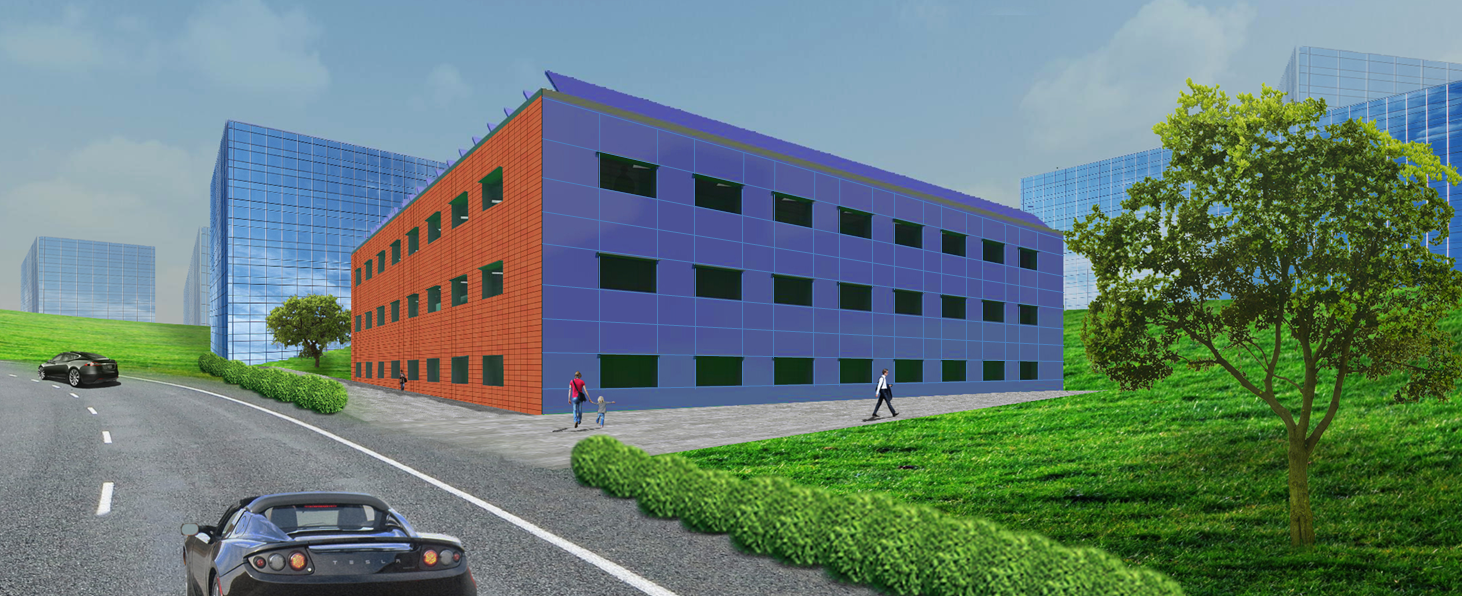
Once the building form was confirmed via optimisation the architect exported the DesignBuilder model geometry to Revit to enable work on the detailed architectural design.
Detailed design - "systems" optimisation
Having confirmed the optimal fabric characteristics to minimise heating and cooling loads the design team set to work on the systems required to meet those loads in the most cost-effective way, with the aim being to minimise site energy consumption then to match any residual consumption with renewable energy generation such as PV.
The variables considered in the second optimisation were:
- 4 different HVAC systems: Variable air volume (VAV); Fan coil units (FCU); Ground source heat pump (GSHP); Water-to-air variable refrigerant flow from ground loop (VRF).
- 3 different lighting systems, each with and without daylight controls: LED; T5; CFL.
- PV options: Roof-mounted panels; Building-integrated PV; Shading devices (overhangs).
- Insulation, thermal mass and external shading were included again to ensure that their effects were taken into full consideration alongside the HVAC system characteristics.
The initial load reduction optimisation results indicated no shading (louvers only) suggesting that we should also consider less drastic shading devices such as overhangs to ensure we identified the optimum trade-off between the conflicting need for cooling and daylighting. Otherwise the objectives and constraint applied were as the load reduction optimisation and the results showed a large spread of cost and performance as shown in the graph below:
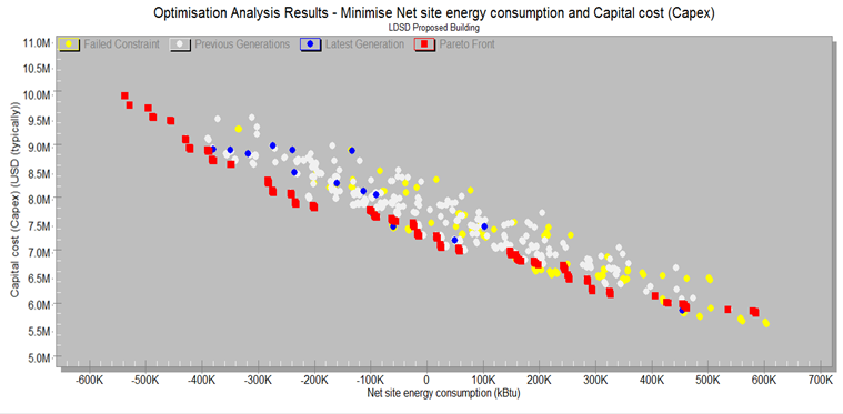
Herein lies one of the major benefits offered by optimisation. No longer do you have to discuss 1, 2 or 3 options with the client...using the optimisation results you can have a fully-informed discussion to identify where the client wishes to be on the cost-performance spectrum. Do they want maximum performance at high cost? Or the opposite? Or do they want to explore the region closer to the origin where the best "trade-off" between cost and performance often lies? The competition brief was to achieve net-zero so we focused on the Pareto-optimal solutions around the zero net site energy consumption line. The cost-optimal solutions identified from the systems optimisation were:
- LED lighting with daylight control.
- Shading using 0.5m deep overhangs was preferred on all but the East façade. A reduced shading depth of 0.3m was preferred on the East façade due to the overall benefit of early-morning solar gain.
- The maximum number of roof-mounted PV panels plus BIPV on the South façade only. The more BIPV added to the design, the more the building becomes a net energy contributor, but at increased construction cost.
- 0.5m deep PV shading devices used as overhangs only on the South façade, the remainder being standard shading.
- VRF (with ground loop) provided the best balance between cost and performance. Whilst the GSHP system with heated floors and chilled beams provided the best theoretical performance it wasn't ideal in combination with the mixed-mode strategy.
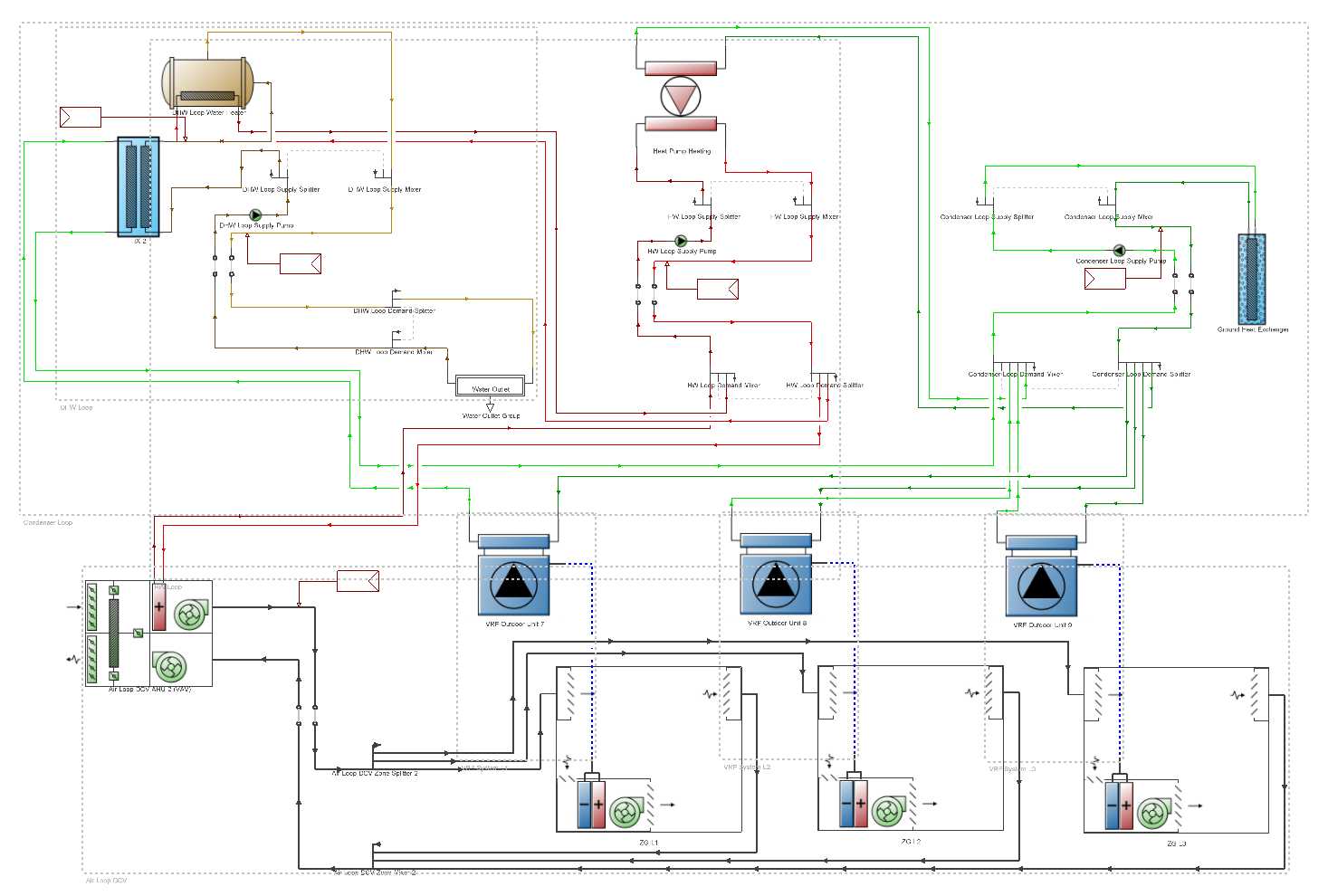
Given the limited time available for the competition we decided to focus our efforts on the VRF system shown schematically below incorporating: Ground source condensor; refrigerant heat recovery between zones; condenser heat recovery to pre-heat DHWS; DOAS for primary ventilation with sensible and latent heat recovery and CO2 demand control; separate water-to-water heat pump for DHWS and AHU pre-heat coil; mixed-mode natural ventilation.
Fine-tuning the design
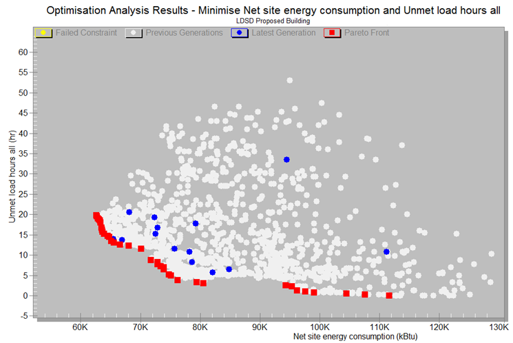
With the main building systems selected the final stage in the process was to fine-tune the HVAC control settings to further improve comfort and minimise energy consumption and unmet load hours. As an innovative extension of the HVAC design, the heating and cooling setback and the natural ventilation setpoint temperatures were optimised as below. To achieve this unmet load hours were used as one of the optimisation objectives:
|
System |
Optimum setting (oF) |
Unmet load hours |
|
Heating setback |
39.2 |
Heating = 17 |
|
Cooling setback |
89.6 |
Cooling = 0 |
|
Natural ventilation setpoint |
72.8 |
N/A |
DesignBuilder's integrated CFD and daylighting analysis tools were used to confirm that the design met good practise requirements. The same model geometry and basic data was used for all analyses eliminating the need to import and export between different programs.
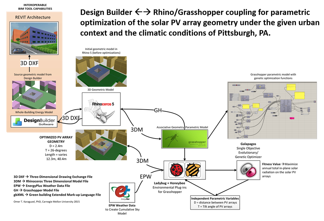
The team realised at the outset that renewable energy contributions were very likely to be required given the climate zone and site constraints, and we were fortunate to have some significant PV design expertise in our team. The DesignBuilder model was exported to Rhino and Grasshopper where the PV configuration was optimized. The final design confirmed an optimum panel spacing of 2.4m with a slope angle of 26 degrees to minimise over-shading from adjacent panels and maximise incident solar radiation taking into account shading from neighboring buildings. The detailed PV design resulted in a PV capacity of 216 kWp enabling the residual energy consumption to be met by the PV with a very small excess in generating capacity.
DesignBuilder is able to export EnergyPlus simulation results as the boundary conditions for a CFD analysis which proved to be very useful when analysing natural and mechanical ventilation performance during operation.
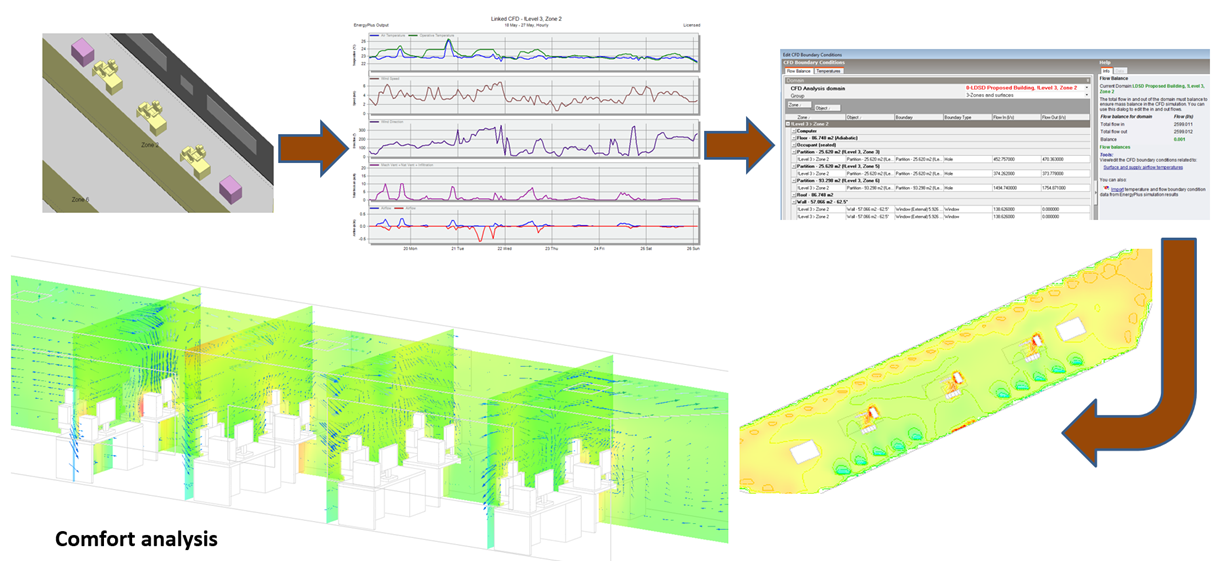
The team was also able to run Air Change Effectiveness (ACE) calculations using DesignBuilder CFD to ensure that there was suitable mixing of zone air from mechanical ventilation supply diffuser.
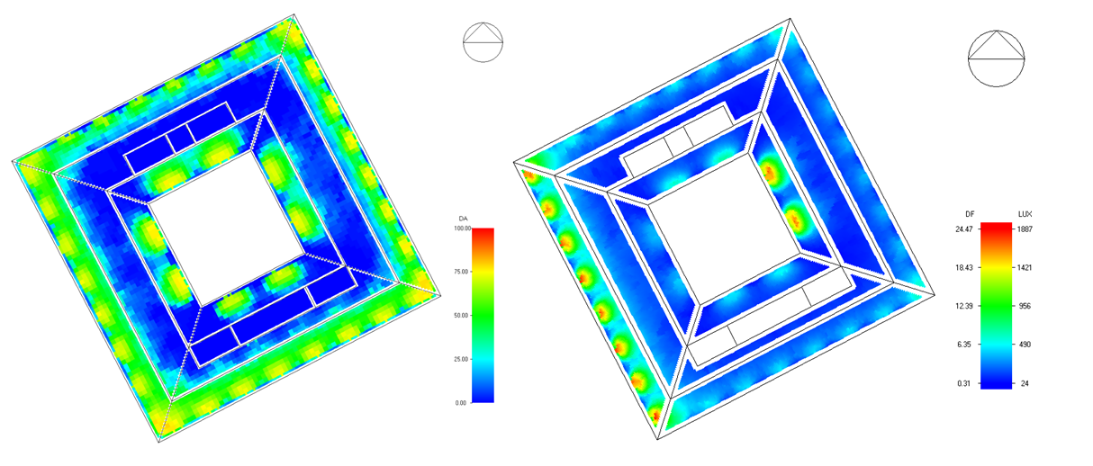
Radiance and Daysim calculations were used to check building daylight performance including illuminance under design conditions and daylight autonomy (sDA300/50%):
Results
The competition required the teams to present results in different ways. The main output was the comparison between the ASHRAE 90.1 baseline building and our proposed building (the competition entry). The EUI of the baseline building (created from the proposed building using our new baseline generator tool) was around 47 kBTU/ft2.year whereas the EUI of our proposed building was 17 kBTU/ft2.year, a 64% reduction on the baseline.
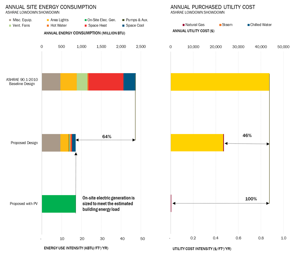
These results were selected for one possible design permutation from the Pareto front of optimal designs. We could equally have selected a design with a much greater net energy contribution but at significantly greater construction cost
So...how low do you want to go and at what cost...DesignBuilder provided the team with the advanced cost-benefit analysis tools to be able to make that assessment.
Acknowledgements
DesignBuilder would like to express our thanks for the hard work, expertise and enthusiasm of the team members that made this such a rewarding process for all involved.
For more details on the competition see:
